Blog
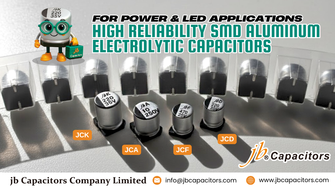
High Reliability SMD Aluminum Electrolytic Capacitors for Power & LED Applications
Aluminum electrolytics often define the lifetime of power supplies due to thermal stress and ESR-induced heating. This guide explains the physics, failure modes, and design practices that turn jb® SMD families into reliable building blocks for SMPS, DC/DC rails, and LED drivers.
Engineer pain points addressed. 1) Lifetime limited by internal temperature rise and electrolyte loss. 2) Catastrophic venting when gas builds up under abusive ripple or reverse bias. 3) Mechanical cracking or lifted parts after reflow and vibration. The jb® SMD portfolio is optimized to minimize AC losses, manage gas generation, and survive SMT plus field vibration while maintaining consistent impedance across operating bands.
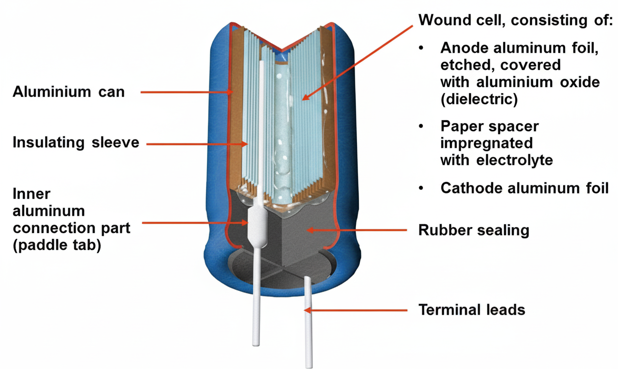
How Aluminum Electrolytics Work
The anode aluminum foil is etched to increase area and anodized to form a thin Al2O3 dielectric. Paper spacers hold electrolyte that serves as the true cathode in contact with the cathode foil. Capacitance density comes from the extremely thin dielectric and large etched surface. These advantages trade off against higher ESR and lower self-resonant frequency compared with film or MLCCs.
Why Lower ESR Extends Lifetime
Ripple current produces I2·ESR heating that accelerates electrolyte evaporation and increases impedance over time. Reducing ESR lowers AC loss and temperature rise, which improves ripple capability and slows aging. A practical starting point is
ESRmax ≈ ΔVripple / Iripple, then validate across frequency and temperature with worst-case load steps.
Designed for Predictable, Safe End-of-Life
Gas generation from abuse conditions can raise internal pressure. jb® SMD parts integrate pressure-relief vents that open in a controlled way, avoiding case rupture and allowing graceful shutdown. This structure, combined with low ESR chemistry, reduces the probability of sudden failures in power and lighting systems.
SMT Robustness and Mechanical Reliability
Reflow integrity. Construction supports lead-free reflow profiles when footprint land patterns follow datasheet keep-outs. Avoid excessive double reflow and verify peak body temperature to protect seals.
Vibration readiness. Reinforced terminations and can geometry help maintain solder joint reliability in high-vibration environments common to industrial power and outdoor LED luminaires.
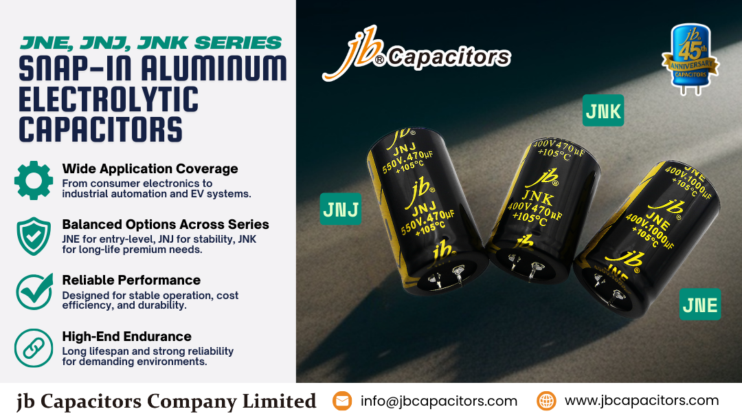
Series Mapping to Use Cases
Match final selection to datasheet limits for voltage, ripple current, size code, and endurance.
jb® JCS — 85 °C, 2000 h, standard ESR. Ideal for consumer SMPS, auxiliary rails, set-top boxes, general-purpose filtering.
jb® JCK — 105 °C, 1000–2000 h, low ESR. Recommended for DC/DC conversion, battery chargers, TV power boards.
jb® JCD — 105 °C, 2000 h, low impedance. Best for telecom, PoE systems, networking equipment, stable filtering.
jb® JCF — 105 °C, 2000–5000 h, ultra-low impedance. Designed for LED drivers and industrial SMPS where heat and ripple are critical.
Design Notes that Protect Lifetime
Place the bulk SMD electrolytic close to the switching stage to minimize loop area and ESL. Parallel MLCCs to suppress high-frequency ripple and avoid anti-resonance notches. For ambient temperatures above 60 °C, keep thermal headroom and consider 10–20% voltage derating. Parallel electrolytics can share ripple current and reduce effective ESR when space permits.
Cross-Reference and Sourcing Continuity
jb® maintains a broad SMD lineup with spec-matched options to leading brands. Request our cross-reference to accelerate qualification and secure stable supply.
Q&A: Frequently Asked Design Questions
Why do SMD aluminum electrolytic capacitors often determine the lifetime of power supplies?
Which jb® SMD series are recommended for LED drivers and high ambient heat?
- Recommended: JCF due to ultra-low impedance and 105 °C endurance (2000–5000 h).
- Benefits: Lower thermal rise, reduced flicker risk in compact luminaires.
- When to prioritize: High power density or restricted airflow applications.
How can ripple current capability be improved without increasing capacitor size?
Can jb® SMD electrolytic capacitors serve as drop-in replacements for leading brands?
- Yes. Voltage, capacitance, case size, ESR, ripple rating, and endurance can be matched.
- Recommendation: Request cross-reference mapping for faster qualification and sourcing continuity.
How to ensure mechanical reliability under vibration and reflow stress?
When should voltage derating be applied?
- Apply 10–20% derating above 60 °C ambient.
- Critical in LED drivers, compact chargers, and thermally constrained designs.
- Helps reduce leakage current and slow electrolyte depletion.
Always validate with the official datasheet. Measure ripple current and temperature rise on bench under worst-case load.